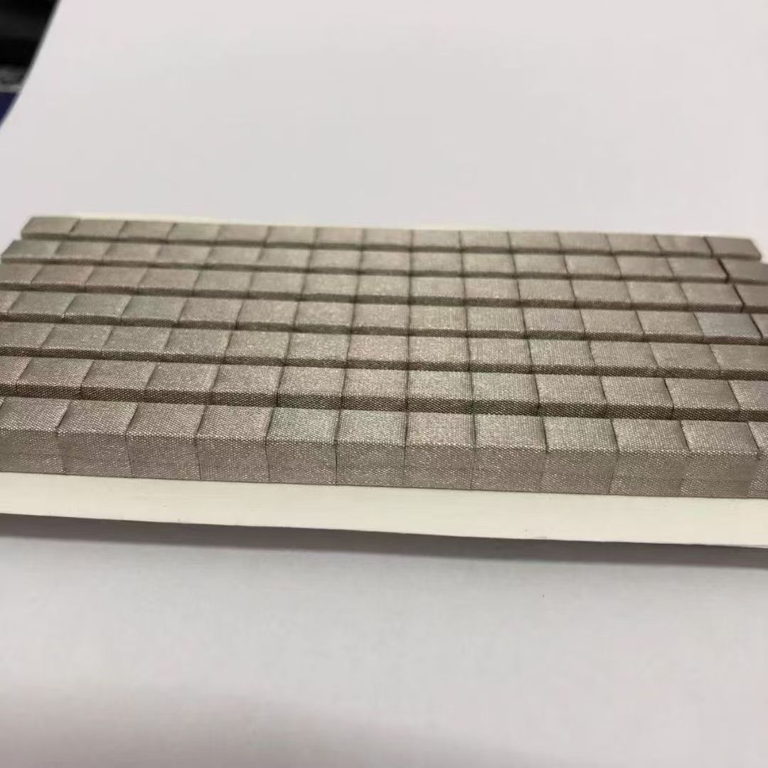
EMC testing often fails not at the radio but at the seam. The shielding gasket — how it contacts, how much it compresses, how it ages — decides whether 3 GHz stays inside the enclosure. This guide condenses the design checks we run before die-cutting any EMI gasket.
1. Seam gap and gasket deflection
Measure the real seam variation across the enclosure, including warp after screws are torqued. The gasket must compress within its working range at the LARGEST gap, not the nominal one. Design compression at 20–40% of free height for conductive foam — enough for stable contact, not so much that hinge deflection appears.
2. Contact resistance, not just shielding dB
Datasheets quote shielding effectiveness, but field failures trace to contact resistance rising over time: oxidation, fretting, loss of compression. Specify gaskets with stable contact resistance (<0.05 Ω/in) and check the mating surface finish. Anodized aluminum needs the anodic layer broken through — via conductive adhesive or mechanical bite — or the gasket does nothing.
3. Material families
| Type | Strength | Watch for |
|---|---|---|
| Conductive foam (Ni/Cu plated) | Low closing force, cheap | Plating wear under sliding |
| Fabric-over-foam | Good abrasion life | Narrow seam designs only |
| Cu/Al foil tape gaskets | Excellent conductivity | Not compressible — needs flat mating |
| Finger stock (extruded) | High cycling life | Not die-cut; different supply chain |
4. Dual-function designs
Where the seam must also seal water or dust, use a dual-function gasket: conductive layer inside, elastomer seal outside. These laminated die-cuts avoid stacking two separate gaskets in a gap that only fits one.
ROTADIE die-cuts all four families above and provides compression and contact-resistance data per lot — so your EMC design review is supported by numbers, not adjectives.